
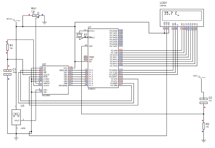
This simple project interface LM35 which is a very common Temperature Sensor giving high precision reading in terms of Analog Voltage with most popular 8051 Microcontroller AT89C51. LM35 gives analog reading and microcontroller process digital data so we have to use a midway converter from Analog to Digital i.e. AD0804 and display the result of a temperature on LCD.
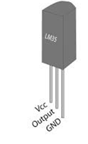
Temperature Sensor (LM35):
LM35 looks like a transistor it will give you temperature in Celsius in terms of millivolt. For example if the temperature is 25 C its output will give you 0.25V provided that you must supply at least 1V to it. Here how it looks:
Analog to Digital Converter (ADC0804):
An analog-to-digital converter is a device that converts a continuous physical quantity (usually voltage) to a digital number that represents the quantity’s amplitude.
The conversion involves quantization of the input, so it necessarily introduces a small amount of error. Instead of doing a single conversion, an ADC often performs the conversions (“samples” the input) periodically. The result is a sequence of digital values that have converted a continuous-time and continuous-amplitude analog signal to a discrete-time and discrete-amplitude digital signal. See Connection Diagram below:

From ADC these digital signals are sent to Microcontroller which displays the temperature of that environment.
- SPAN Adjust
These A/Ds have been designed to accommodate a 5 VDC, 2.5 VDC or an adjusted voltage reference. This has been achieved in the design of the IC as shown in Figure. Notice that the reference voltage for the IC is either 1⁄2 of the voltage applied to the VCC supply pin, or is equal to the voltage that is externally forced at the VREF/2 pin. This allows for a ratio metric voltage reference using the VCC supply, a 5VDC reference voltage can be used for the VCC supply or a voltage less than 2.5 VDC can be applied to the VREF/2 input for increased application flexibility. The internal gain to the VREF/2 input is 2, making the full-scale differential input voltage twice the voltage at pin 9.
An example of the use of an adjusted reference voltage is to accommodate a reduced span—or dynamic voltage range of the analog input voltage. If the analog input voltage were to range from 0.5 VDC to 3.5 VDC, instead of 0V to 5 VDC, the span would be 3V. With 0.5 VDC applied to the VIN(−) pin to absorb the offset, the reference voltage can be made equal to 1⁄2 of the 3V span or 1.5 VDC. The A/D now will encode the VIN(+) signal from 0.5V to 3.5 V with the 0.5V input corresponding to zero and the 3.5 VDC input corresponding to full-scale. The full 8 bits of resolution are therefore applied over this reduced analog input voltage range.
- ADC reads the temperature from LM35 sensor whose voltage is a function of present room temperature. When temperature is 20 degree it send 200mV to ADC and we have used Vref/2 pin to 700mV or changeable value for span adjustment. ADC translates the 200mV to digital and send it to AT89C51.
Please see the simulation below:
LCD Interface with AT89C51
How to interface LCD with AT89C51 please visit here
Program Code:
Please see the Program code:
#include reg51.h
#define input P1;

double newtemp,pass1,pass2,T;	//variables used

  //LCD
sbit rs = P3^0;        //register select pin
sbit rw = P3^1;        //read write pin
sbit e = P3^2;        //enable pin

//ADC
sbit rd=P3^7;		   //defines rd pin of ADC use for reading purposes
sbit wr=P3^6;		   // define wr pin of ADC use for writing purposes
sbit intr=P3^4;		   //defines intr pin use for sending interrupts from microcontroller

void delay(unsigned int time)    //Function to provide time delay in msec.

{

int i,j ;
for(i=0;i<time;i++)
for(j=0;j<1275;j++);

}

double adc()  // Function to read the values from ADC and send to controller.
{
double temp;
rd=1;
wr=0;
delay(1);
wr=1;
while(intr==1);
{rd=0;
temp=input;
delay(3);}
return temp;
}


void lcdcmd(unsigned char item)    //Function to send commands to LCD see command tables in LCD Link

{
P2 = item;
rs= 0;
rw=0;
e=1;						  //send to high to low pulse while writing
delay(1);
e=0;
}

void lcddata(double item)    //Function to send data to LCD

{

P2 = item;
rs= 1;
rw=0;
e=1;						  //send high to low pulse while writing
delay(1);
e=0;
}

void disp_temp(double num)            //displays number on LCD
{
unsigned char UnitDigit  = 0;  //It will contain unit digit of number
unsigned char TenthDigit = 0;  //It will contain 10th position digit of number
unsigned char HundDigit = 0;  //It will contain 100th position digit of number
unsigned char decimal=0;	  //It will contain the decimal position of number
int point;
point=num*10;

HundDigit=(num/100);

if( HundDigit != 0)	          // If it is zero, then don't display
lcddata(HundDigit+0x30);	  // Make Character of HundDigit and then display it on LCD

TenthDigit = num - HundDigit*100;  // Findout Tenth Digit

TenthDigit = TenthDigit/10;

if (HundDigit==0 && TenthDigit==0){} 	          // If it is zero, then don't display
else
lcddata(TenthDigit+0x30);	  // Make Char of TenthDigit and then display it on LCD


UnitDigit = num - HundDigit*100;
UnitDigit = UnitDigit - TenthDigit*10;

lcddata(UnitDigit+0x30);	  // Make Char of UnitDigit and then display it on LCD
lcddata('.');
decimal=(point%10);
lcddata (decimal+0x30);		  // Make Char of Decimal Digit and then display it on LCD

lcddata(' '); lcddata('C');


}


void read(){	  // Displays "READING" while controller reads from ADC
lcdcmd(0x0E);    //turn display ON for cursor blinking
lcdcmd(0x01);    //clear screen
lcdcmd(0x06); 	 //increment cursor
lcddata('R');lcddata('E');lcddata('A');lcddata('D');lcddata('I');lcddata('N');lcddata('G');lcddata(' ');
}


void main()

{
P0=0x00;				//intialize port 0 to low use while controller reads the temperature from
                                        //ADC

read();					// show reading on LCD while controller reads from ADC

while(1){			   // use for checking errors while reading the value from ADC
newtemp=adc();			//reads first value  from ADC
delay(60);			//waits 60 msec
pass1=adc();			// reads the Second value from ADC
delay(60);			// waits 60 msec
   if (newtemp==pass1){	        //compare first and second value
        break;			 // if first and second value is same breaks the loop
	}

}

while(1){			   //enters in the permanent loop
T=160;                             //set reference voltage acting multiplier factor for temperature accuration

newtemp=(((newtemp*T)/255));      //converts the temperature value according to reference adjusted in decimal
lcdcmd(0x0E);                     //turn display ON for cursor blinking
lcdcmd(0x01);                     //clear screen
lcdcmd(0x06);                     //increment
disp_temp(newtemp);	          //show temperature
delay(300);			 //waits 3sec before re-measure the value of temperature

while(1){			  // re-measure the value from ADC but this time double check
newtemp=adc();
delay(60);
pass1=adc();
delay(60);
pass2=adc();
   if (newtemp==pass1){
      if(pass1==pass2){
	    break;		}
	}

}
                                   // end ADC while loo[
	   }			  // end while permanent loop
}				 // end main loop
These double checks enables to remove errors when you do it on a hardware. Have a Goodluck running this Project 🙂
If you have any questions or suggestions please leave us a comment below: