
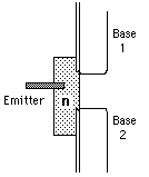
A uni-junction transistor (UJT) is an electronic semiconductor device that has only one junction. The UJT has three terminals: an emitter (E) and two bases (B1 and B2). The base is formed by lightly doped n-type bar of silicon. Two ohmic contacts B1 and B2 are attached at its ends. The emitter is of p-type and it is heavily doped. The resistance between B1 and B2, when the emitter is open-circuit is called interbase resistance (RBB or r’BB).
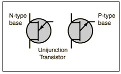
Unijunction Transistor has different characteristics from ordinary bipolar transistor. It is a pulse generator with the trigger or control signal applied at the emitter. An n-type unijunction transistor (left symbol in above picture) is made by implanting a small p-type emitter probe in a bar of n-type silicon. The emitter probe is offset from the center of the bar and there are two bases as shown below:
N-Type UJT
Types of UJT’s
- The original unijunction transistor (UJT) consist of a bar of N type semiconductor material into which P type material has been diffused somewhere along its length, defining the device parameter ‘η’. The 2N2646 is the most commonly used version of the UJT.
- The complementary unijunction transistor (CUJT) consist of a bar of P type semiconductor material into which N type material has been diffused somewhere along its length, defining the device parameter ‘η’. The 2N6114 is one version of the CUJT.
- The programmable unijunction transistor (PUT) consists of four P-N layers and has an anode and a cathode connected to the first and the last layer, and a gate connected to one of the inner layers.
Working of UJT
The emitter terminal does not inject current into the base region until its voltage reaches Vp. Once Vp is reached the base circuit conducts and a positive pulse appears at the B1 terminal and a negative pulse at B2. Because the base region is very lightly doped, the additional current (actually charges in the base region) causes conductivity modulation which reduces the resistance of the portion of the base between the emitter junction and the B2 terminal. This reduction in resistance means that the emitter junction is more forward biased, and so even more current is injected. Overall, the effect is a negative resistance at the emitter terminal. This is what makes the UJT useful, especially in simple oscillator circuits.
The very basic specifications of a UJT are:
- Vbb (max) :- The maximum interbase voltage that can be applied to the UJT.
- Rbb :- The interbase resistance of the UJT.
- η :- The intrinsic standoff ratio which defines Vp.
- Ip :- The peak point emitter current.
Characteristic’s Curve of UJT:
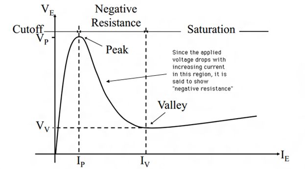
Characteristic’s Curve of UJT
The negative resistance region in the characteristic of the unijunction transistor makes it useful for constructing relaxation oscillators.
Basic UJT Biasing:
In order to make UJT working it should be biased first. Biasing Conditions and biased UJT diagram is shown below:
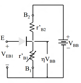
Biasing of UJT
- Vr’B1 = η VBB where is the standoff ratio.
- At Vp = η VBB + Vpn , (where Vpn is the barrier potential of pn junction) The UJT turns on and operates in a negative resistance region as shown in characteristics curve up to a certain value of IE. Afterwards it becomes saturated and IE increases rapidly with VE
- UJT will not operate if VEB1 < Vr’B1 + Vpn as IE = 0 and pn junction is not forward biased.
Where:
- r’B1 and r’B2 are the internal dynamic resistance or base resistances.
- r’BB is the inter-base resistance which is r’BB = r’B1 + r’B2.
- r’B1 varies inversely with emitter current IE.
- r’B1 can range from several thousand ohm’s to tens of ohm’s depending on IE.
Applications of UJT:
- UJT can be used to build simple oscillators like relaxation oscillators.
- UJT can also be used as trigger device for SCR (Silicon control rectifier) and TRIACS (Triode for Alternating current).
- Also used as non-sinusoidal oscillators, saw tooth generators, phase control and timing circuit.
- Also used to measure magnetic flux using Hall’s Effect.