
Interface LED with AT89C51
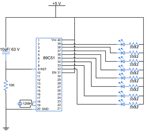
AT89C51 is a 40 pin microcontroller which belongs to 8051 series of microcontroller. It has four ports each of 8 bits P0, P1, P2 and P3.The AT89C51 has 4K bytes of programmable flash. The port P0 covers the pin 32 to pin 39, the port P1 covers the pin 1 to pin 8, the port P2 covers the pin 21 to pin 28 and the port P3 covers the pin 10 to pin 17. Pin 9 is the reset pin. The reset is active high. Whenever the controller is given supply, the reset pin must be given a high signal to reset the controller and bring the program counter to the starting address 0x0000. The controller can be reset by manually connecting a switch or by connecting a combination of resistor and capacitor as shown in the circuit diagram. A 11.059 MHz crystal is connected between pin 18 pin 19. Pin 40 is Vcc and pin 20 is ground. Pin 31, is connected to Vcc as we are using the internal memory of the controller (see Datasheet for details). LEDs are connected to the port P0. LEDs need approximately 10mA current to flow through them in order to glow at maximum intensity. However the output of the controller is not sufficient enough to drive the LEDs, so LEDs are connected in the reverse order and they run on negative logic i.e., whenever 1 is given on any pin of the port, the LED will switch off and when logic 0 is provided the LED will glow at full intensity. As soon as we provide supply to the controller, the LEDs start blinking i.e., they become on for a certain time duration and then become off for the same time duration. This delay is provided by calling the delay function. The values inside the delay function have been set to provide a delay in multiples of millisecond (delay (100) will provide a delay of 100 millisecond).
- Build the circuit on Proteus and write the code on Keil. Also generate a HEX file using keil.
- Verify your circuit and code on software and then burn the HEX file on AT89C51 using G540 burner as already explained here.
- Implement the circuit on Breadboard.
Code is given as:
#include reg51.h //include directives for 8051 microcontroller
void delay(int time){ //Produces delay in msec
 int a,b;
 for (a=0;a<time;a++){
  for (b=0;b<1275;b++){} //1275 is due to 11.059 MHz crystal
 }
}
void main(){
 while(1){ //infinite loop
 P0=0x00; //P0 will have a 0 logic means 0 volt. LED will glow
 delay(100); //100msec delay
 P0=0xFF; //P0 will have a 1 logic means 5 volt. LED will be off
 delay(100); //100msec delay
 }
}