
This article assumes that you have some concepts of Signals and Systems and basic knowledge of communication systems.
Content of this article is adapted from “Digital Communication by John G. Proakis”
In the last article: Relationship of Bandpass and Lowpass Signals, we discussed the importance of Bandpass and Lowpass signals and representation of bandpass signal in terms of its low-pass counterpart by shifting the carrier frequency and taking its real part:
[latex]x(t) = \text{Re} \{x_l(t) e^{j2\pi f_o t} \}[/latex]
And recovery of low-pass signal from its band-pass counterpart by using Hilbert transformation:
[latex]x_l(t) = \{ x(t) + j \hat{x}(t) \}e^{-j2\pi f_o t}[/latex]
In this article, we will discuss represent these two complex equations in their rectangular form which is also known as the IQ representation. This form is useful to us in understanding the design of IQ modulator or Software-Defined Radio’s. Since, [latex]x_l(t)[/latex] is a complex signal, we can write in rectangular form as:
[latex]x_l(t) = x_i(t) + jx_q(t)[/latex]
and the bandpass signal is given as: [latex]x(t) = \text{Re} \{ x_l(t) e^{j2\pi f_o t} \}[/latex]. Then we can combine these two equations to form:
[latex]x(t) = \text{Re} \{ x_i(t) e^{j 2\pi f_o t} + jx_q e^{j 2 \pi f_o t} \}[/latex]
Applying Euler identity and taking real parts from the above equation and we have:
[latex]x(t) = x_i(t) \cos (2 \pi f_o t) – x_q(t) \sin (2 \pi f_o t)[/latex]
Some interesting facts about above equation:
- Both [latex]x_i(t)[/latex] and [latex]x_q(t)[/latex] are real signals whereas, [latex]x_l(t)[/latex] is a complex signal.
- [latex]x_i(t)[/latex] & [latex]x_q(t)[/latex] are Lowpass signal.
- [latex]x_i(t)[/latex] & [latex]x_q(t)[/latex] are orthogonal signals.
This form gives us a more clear picture of the working principle of a Software-Defined radio. We simply design two real signals [latex]x_i(t)[/latex] and [latex]x_q(t)[/latex]. We multiply these two signals with [latex]\cos(2 \pi f_o t)[/latex] and [latex]- \sin(2 \pi f_o t)[/latex] respectively, which makes them orthogonal signals and finally add them to form a complete band-pass signal. In Digital Communication, this process is also called Up-conversion. A pictorial representation of the working principle of Software-Defined Radio is given below:
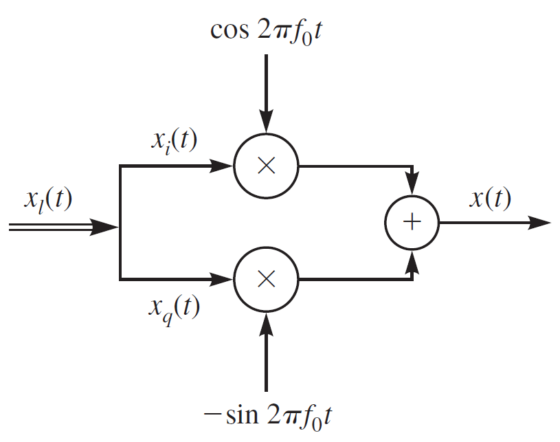
Source: Digital Communication by J.Proakis
A Down-conversion or Recovering Lowpass signal from Bandpass in IQ form is given as:
[latex]x_l(t) = \{ x(t) + j \hat{x}(t) \}e^{-j2\pi f_o t}[/latex]
Applying Euler identity to above equation we get:
[latex] x_l(t) = x(t) \cos(2 \pi f_o t) – j x(t) \sin(2 \pi f_o t) + j\hat{x}(t) \cos(2 \pi f_o t) + \hat{x}(t) \sin(2 \pi f_o t)[/latex]
Using rectangular form of [latex] x_l(t)[/latex] and writing real and imaginary parts separately, we get:
[latex] x_i(t) = x(t) \cos(2 \pi f_o t) + \hat{x}(t) \sin(2 \pi f_o t) [/latex]
[latex] x_q(t) = \hat{x}(t) \cos(2 \pi f_o t) – x(t) \sin(2 \pi f_o t) [/latex]
These two equations are used to design the IQ demodulator/receiver. Pictorial representation is given below:
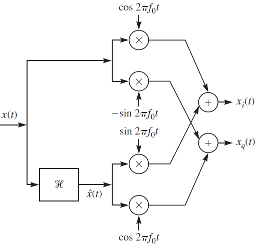
Source: Digital Communication by J. Proakis
Figure 1 and Figure 2 represent the theoretical concept of the working of an IQ modulator/demodulator. This representation is very crucial in understanding the concepts of modern digital communication. But, this representation is cumbersome to understand, and that’s why it is recommended to use complex polar form representation instead of rectangular representation. In the next articles, we will be using the polar form representation. In practice, taking Hilbert Transformation of a received signal is not suitable as we are directly dealing with the bandpass signal, which is, of course, a high-frequency signal, and this means developing high-frequency electronics. So, in practice we take Bandpass signal [latex]x(t)[/latex] downconvert it by multiplying it with [latex]e^{-j 2 \pi f_o t}[/latex] and then passing it through a Lowpass filter [latex]h_{lp}(t)[/latex]. So, in the frequency domain we have:
[latex]X_l(f) = X(f+f_o) H_{lp}(f)[/latex]
Where, [latex]H_{lp}(f) = u(f+f_o) – u(f-f_o)[/latex]. The bandwidth of this lowpass filter is at least as large as the bandwidth of the bandpass signal. We are not proving why this lowpass filter method gives the same result as with Hilbert transform, but you can always use WolframAlpha to verify. In all our discussion in this article, we came to two significant results:
For Upconversion: [latex]x(t) = \text{Re} \{ x_l(t) e^{j 2 \pi f_o t} \}[/latex]
For Downconversion: [latex]x_l(t) = \text{LPF} \{ x(t) e^{-j 2 \pi f_o t} \}[/latex]
All practical IQ modulator/demodulator and Software-defined Radios use the above two equations as their working principle. In the next article, we will share how we approximate the complete bandpass channel with a simple baseband channel by using these powerful results. If you have any questions or suggestions, do share us a comment.