If you are reading this article, then this means you are already familiar with the concept of Lowpass and Bandpass signals. If not, then it is highly recommended to see Relationship of Bandpass and Lowpass Signals and I/Q Representation for Bandpass & Lowpass Signals. In both of these articles, we have discussed the mathematical relationship of converting a Lowpass baseband signal to bandpass and from a bandpass signal to lowpass. Moreover, we also discussed the IQ representation of these two conversions.
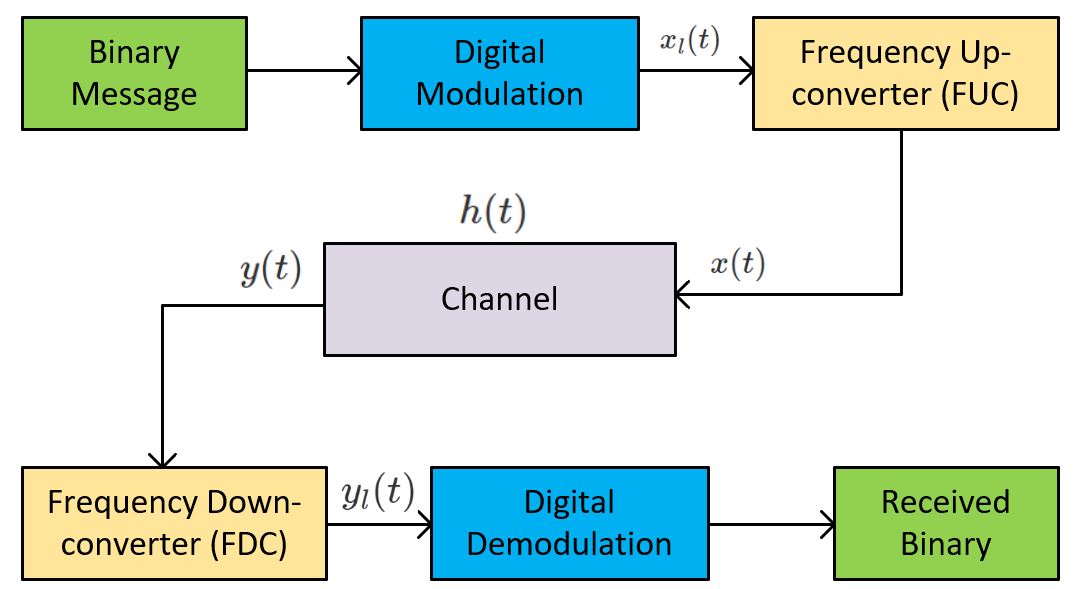
In both articles, our primary motivation was to use baseband signal [latex]x_l(t)[/latex] in all our communication design and then convert it into bandpass signal [latex]x(t)[/latex] for transmission over the air. But we didn’t talk about anything related to what happens when the bandpass signal is transmitted. In this article, we will discuss the role of bandpass channel [latex]h(t)[/latex] and how the received signal [latex]y(t)[/latex] can be expressed in terms of transmitted bandpass signal [latex]x(t)[/latex] and baseband signal [latex]x_l(t)[/latex]. To sum up, here is a pictorial representation of a working of a modern digital communication system:
Given, we receive [latex]y(t)[/latex], then [latex]y(t) = x(t) * h(t)[/latex]. This means we receive a bandpass signal [latex]y(t)[/latex] which is equivalent to transmitted bandpass signal [latex]x(t)[/latex] convolved with bandpass channel [latex]h(t)[/latex]. Lowpass equivalent of a bandpass received signal [latex]y(t)[/latex] is given as:
[latex]\begin{split}
y_l(t) =& \text{LPF } \{ [x(t) * h(t) ] e^{-j2 \pi f_o t} \} \\
=& \text{LPF } \{ x(t) e^{-j 2 \pi f_o t} * h(t) e^{-j 2 \pi f_o t} \} \\
=& \text{LPF } \{ x(t) e^{-j 2 \pi f_o t} \} * LPF \{ h(t) e^{-j 2 \pi f_o t} \} \\
=& x_l(t) * h_l(t)
\end{split}[/latex]
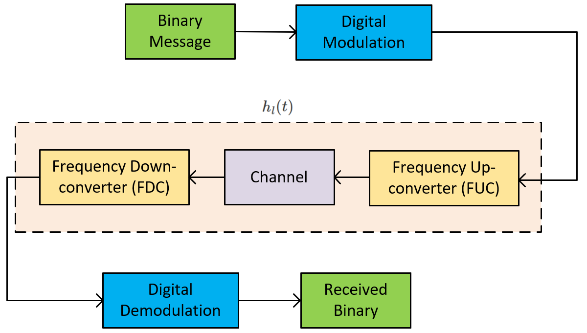
Where in above derivations we have used the linear behavior of lowpass filter and linear property of convolution. From the above result, we can now express all three blocks: {FUC, Channel, FDC} by just a single expression [latex]h_l(t)[/latex] which is known as Baseband Channel:
So, now we can work directly with baseband equivalents of the channel [latex]h_l(t)[/latex], the received baseband signal [latex]y_l(t)[/latex] and the transmitted baseband signal [latex]x_l(t)[/latex] instead of working with their bandpass equivalents.
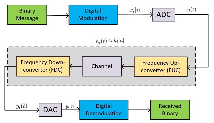
Software Radio Perspective: Since, SDR by definition, works by designing the lowpass signal in software, this means we can apply sampling property to convert [latex]x_l(t)[/latex] to [latex]x_l[n][/latex]. And Digital Signal Processing gave potent tools like Analog to Digital Converter (ADC) and Digital to Analog Converter (DAC) to go back and forth from continuous-time to discrete-time. So, here goes the complete picture:
This makes a straightforward approach to work in the discrete domain directly, and everything we design in the discrete domain works perfectly in a continuous domain, provided the Nyquist criteria is satisfied. Moreover, the channel [latex]h_l(t)[/latex] is represented in discrete domain [latex]h_l[n][/latex] by using the impulse invariance such that [latex]h_l[n] = Th_l(nT)[/latex]. This article explains the power of using the digital domain over the continuous domain and how modern communication systems are designed. If you have any questions or suggestions, do leave us a comment.


