In this tutorial, we will walk you through the steps on how you can simulate a Verilog program in Xilinx Project Navigator. For this tutorial, we have Xilinx ISE 14.4.
Make sure you have installed Xilinx ISE 14.4 or later. Follow the below-mentioned procedure to simulate your first Verilog program.
- Open 32/64-bit Project Navigator.
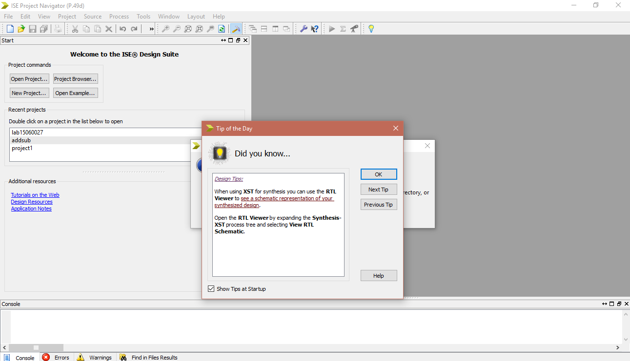
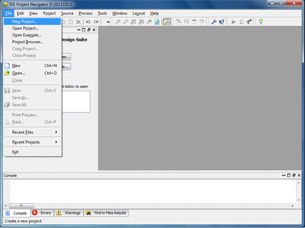
- Click “OK” to close the ‘Tip of the Day’ window that pops up. You can uncheck “Show Tips at Startup” if you do not want the “Tip of the Day” to popup every time you start the tool. Now create a new project by clicking File menu > New Project.
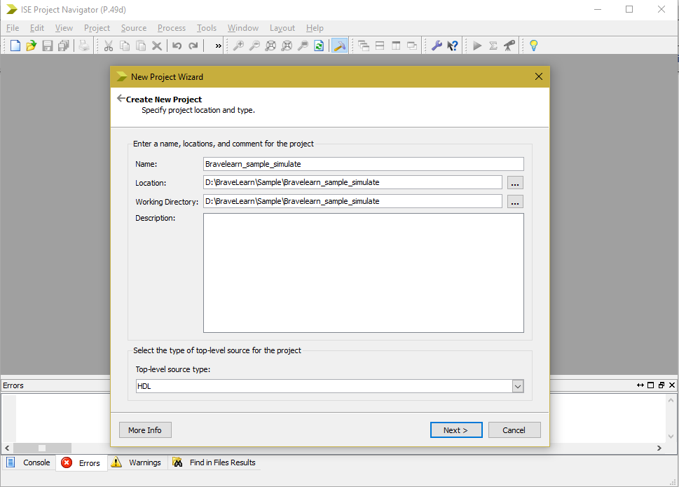
- When the Create New Project window is displayed, choose your working directory (or the directory where you have your program stored) and type your new project name Bravelearn_sample_program in the project name field. Select “Top-level source type” as “HDL”. Add project description if you need
- Click Next and you will go to the “Select the device and design flow for the project” interface. For tutorials on BraveLearn we will select the following device parameters:
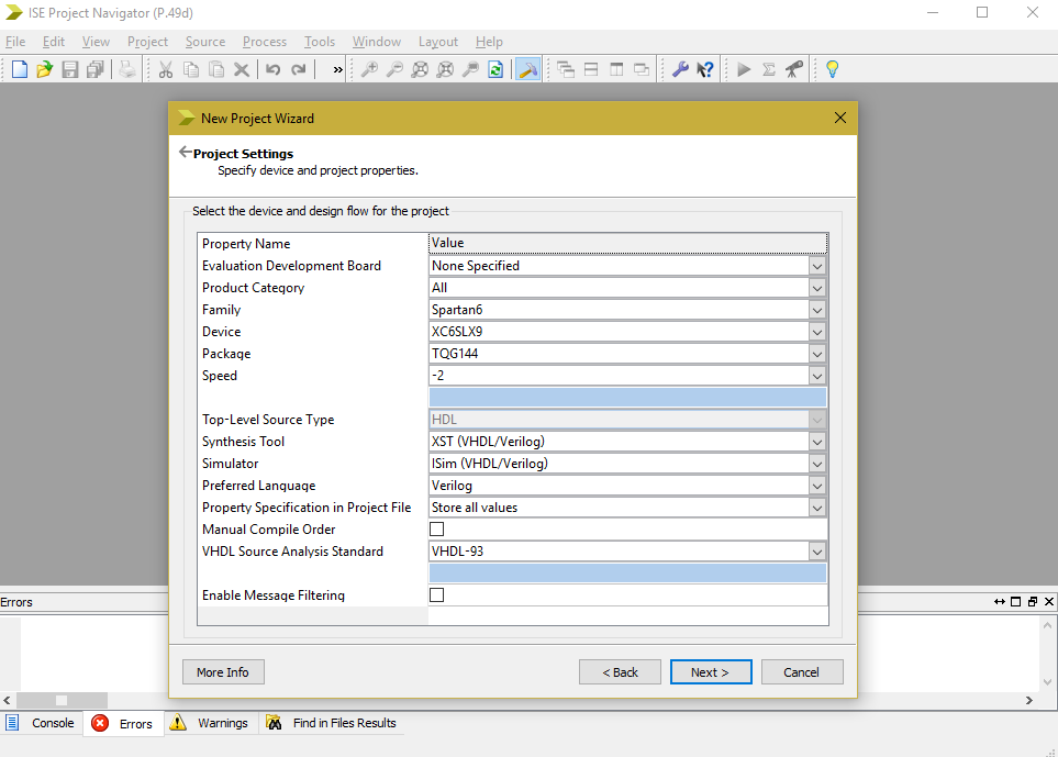
- If you have another FPGA or some other hardware then please change the parameters accordingly. Don’t forget to set preferred language to Verilog as we are coding in Verilog.
- Click Next to view project summary and then click Finish.
- Create New Source You have three options in creating a new source file.
- Option 1: Use the toolbar on the left-hand side of the project navigator window to create a new source. Click on the new source icon (the topmost) to create a new source
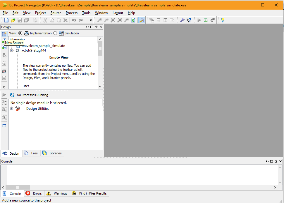
- Option 2: Use the toolbar menu on the top. Project -> New Source to create a new source
- Option 3: Use the project in the “Hierarchy” section of the “Design” tab. Select the project (Bravelearn sample simulate here), right-click and select “New Source” to create a new source.
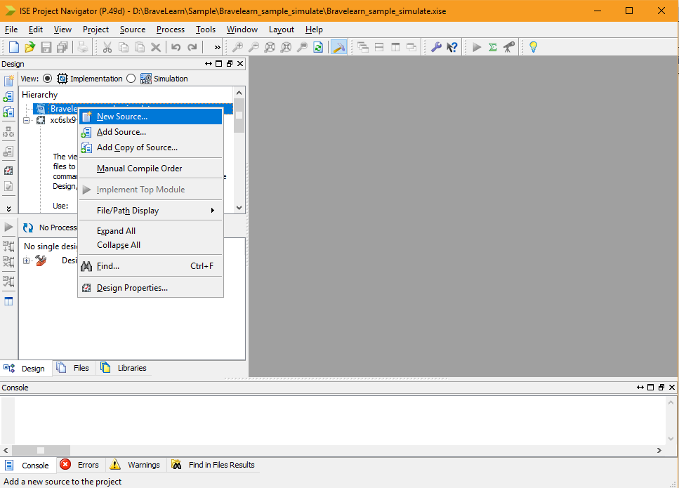
- Option 1: Use the toolbar on the left-hand side of the project navigator window to create a new source. Click on the new source icon (the topmost) to create a new source
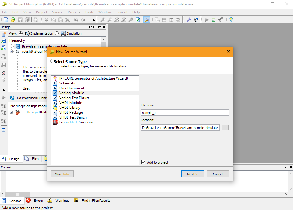
- You will see new source wizard window.In the file name write the name of the module and select Verilog module.
- Now assign port names. You can also use a multi-bit bus instead of single bit input or output. Let ‘a’,’b’ be input ports and ‘c’ be the output port.
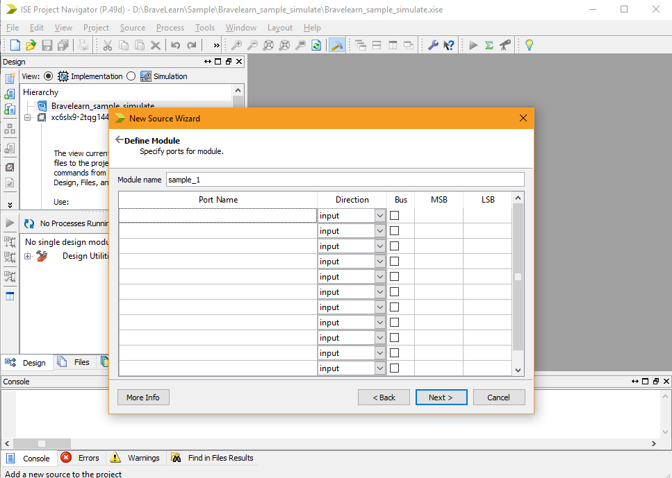
- Click Next to see summary and then click Finish. After pressing finish, A skeleton of your module is created automatically. Now you can write your code the of module.
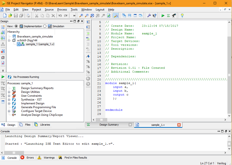
- Write a simple assign statement i.e.
assign c = a+b; - After writing code, verify it is correct by simulating it. To do that select Simulation in Hierarchy view:

- Select your Verilog code, in this case sample_1. Expand lsim simulator in bottom box and double click on Behavioural Check syntax:
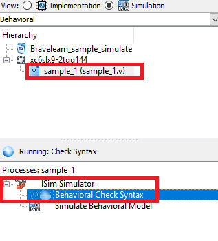
- After checking the syntax of code a green tick will show on Behavioral Check Syntax. Now click on New Source again and instead creating a new Verilog module select Verilog Test Fixture. This will create a testbench.
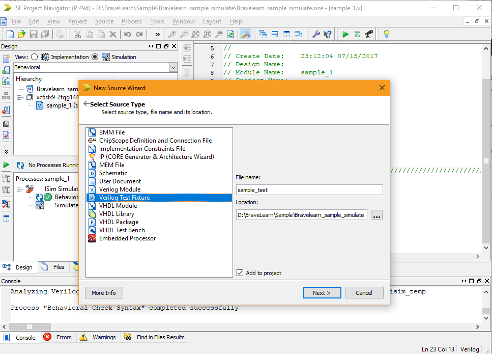
- Select the code for which you want to create a testbench. In this case, it is “sample_1” and click Finish.
- In test bench code define values for variables “a” and “b”.
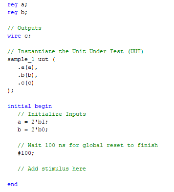
- Select “sample_test” and double click on Behavioral Check Syntax to see if it compiles correctly. If the green tick is shown like it should if you didn’t make any mistakes then double click on Simulate Behavioral Model.
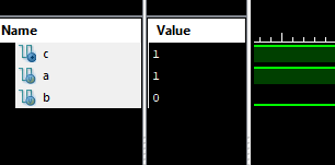
- You can observe from above figure that we have set the value of a=1 and b=0 in binary and output of c=1 as it should be.
Congratulations! If you followed all above steps then you have successfuly learned Xilinx to simulate Verilog programs. You may use ModelSim or Xilinx to code your Verilog programs. However, in next tutorials we will use Xilinx to code Verilog programs and we will show you how you can connect your FPGA with Xilinx.
