
In our previous article “Hierarchical Design of Verilog” we have mentioned few examples and explained how one can design Full Adder using two Half adders.
This example problem will focus on how you can construct 4×2 multiplexer using 2×1 multiplexer in Verilog.
A multiplexer is a device that can transmit several digital signals on one line by selecting certain switches.
For example, in a 2×1 multiplexer, there is one select switch and two data lines. You can select a data line by setting a switch to 0 or 1 as shown in the diagram below:
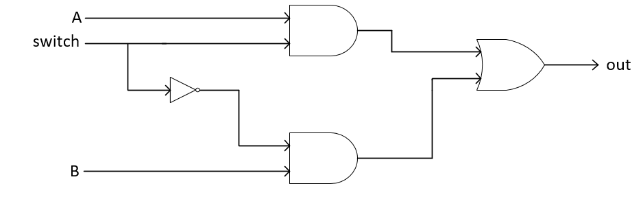
From the above figure, we can observe that if we set a switch to 1 then out will have data line A. As (A AND 1 = A) and due to the presence of NOT gate B data will have no effect on output. Hence, we can have our 2×1 multiplexer.
Truth table for 2×1 mux is given below:
| Input | Output | ||
| A | B | S | Out |
| 0 | 0 | 0 | 0 |
| 0 | 0 | 1 | 0 |
| 0 | 1 | 0 | 1 |
| 0 | 1 | 1 | 0 |
| 1 | 0 | 0 | 0 |
| 1 | 0 | 1 | 1 |
| 1 | 1 | 0 | 1 |
| 1 | 1 | 1 | 1 |
From above table, we can deduce its boolean expression which is simply: [latex]\text{ Out } = AS + BS'[/latex]
we can easily write its Verilog code given below:
Verilog Code for 2×1 Mux
module mux2x1(out,a,b,s);
input a,b,s;
wire and_1,and_2,s_c;
output out;
not (s_c,s);
and (and_1,a,s_c);
and (and_2,b,s);
or (out,and_1,and_2);
endmodule
In a hierarchical design, all we need is to design a small block and construct a big block using these small blocks. Now we have constructed our 2×1 mux we can easily construct 4×2 mux using three of these 2×1 muxes as shown in the block diagram given below:

When S1 is set to HIGH it will select i1 and i3 now if s0 is LOW output will have i1 otherwise i3 and similar for i0 and i2. This combination is shown below:
| S0 | S1 | Out |
| 0 | 0 | i0 |
| 0 | 1 | i1 |
| 1 | 0 | i2 |
| 1 | 1 | i3 |
Focus on the diagram of 2×1 mux and you will get it how this 4×2 mux works. Now using hierarchical designing it is very easy to write Verilog code of 4×2 mux by just instantiating three 2×1 muxes.
Verilog Code for 4×2 Mux
module mux4x2(out,i0,i1,i2,i3,s1,s0);
input i0,i1,i2,i3,s1,s0;
output out;
wire mux1,mux2;
mux2x1 mux_1(mux1,i0,i1,s1);
mux2x1 mux_2(mux2,i2,i3,s1);
mux2x1 mux_3(out,mux1,mux2,s0);
endmodule
This 4×2 mux is tested for selective inputs given below:
| i0 | i1 | i2 | i3 | s0 | s1 | out |
| 1 | 0 | 1 | 1 | 0 | 1 | 0 |
| 0 | 1 | 0 | 0 | 0 | 1 | 1 |
| 0 | 0 | 1 | 0 | 1 | 0 | 1 |
| 0 | 0 | 0 | 1 | 1 | 1 | 1 |
| 1 | 0 | 0 | 0 | 0 | 0 | 1 |
Test Bench code for 4×2 Mux
`timescale 1ns/1ns
module mux4x2_tb;
wire t_out;
reg t_a, t_b, t_c, t_d, t_s1, t_s0;
mux4x2 my_4x2_mux( .i0(t_a), .i1(t_b), .i2(t_c), .i3(t_d), .s1(t_s1), .s0(t_s0), .out(t_out) );
initial
begin
// 1
t_a = 1'b1;
t_b = 1'b0;
t_c = 1'b1;
t_d = 1'b1;
t_s0 = 1'b0;
t_s1 = 1'b1;

#5 //2
t_a = 1'b0;
t_b = 1'b1;
t_c = 1'b0;
t_d = 1'b0;
t_s0 = 1'b0;
t_s1 = 1'b1;


#5 //3
t_a = 1'b0;
t_b = 1'b0;
t_c = 1'b1;
t_d = 1'b0;
t_s0 = 1'b1;
t_s1 = 1'b0;


#5 //4
t_a = 1'b0;
t_b = 1'b0;
t_c = 1'b0;
t_d = 1'b1;
t_s0 = 1'b1;
t_s1 = 1'b1;


#5 //5
t_a = 1'b1;
t_b = 1'b0;
t_c = 1'b0;
t_d = 1'b0;
t_s0 = 1'b0;
t_s1 = 1'b0;

end
endmodule
The simulated result is shown below:
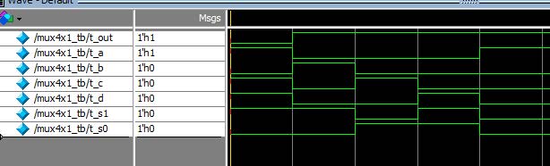
We hope you will find this example interesting, we will keep posting more problems and examples soon. If you have any questions or suggestions please leave us a comment below.