This simple project tells you how to interface 4×3 phone keypad with famous 8051 Microcontroller AT89C51 and displays the numbers on LCD 16×2
If you want to know how to interface LCD with 8051 Please visit here.
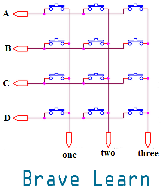
Keypad acts as a Matrix switch as shown below:

These switch matrix is a combination of switches in rows and columns.
Now if we want to detect what switch is pressed we will scan rows and columns. Lets say that we put all rows of the matrix on a digital HIGH by using Microcontroller and then scan each column for a pressed key. Now how to scan each column ? let me explain with an help of an example:
Lets say a user press the button 3 on the keypad:
- We will put all rows on a digital HIGH.
- As the button 3 is pressed the third column will be on digital LOW.
- Now we use such a logic to scan each row again.
- As button 3 is on the first row, it will short the first row to digital LOW.
- Now Microcontroller detects that row A and the third column are on digital LOW.
- So, now AT89C51 knows that you have pressed the button 3.
- It will store this value in an arbitrary variable and displays the value on LCD.
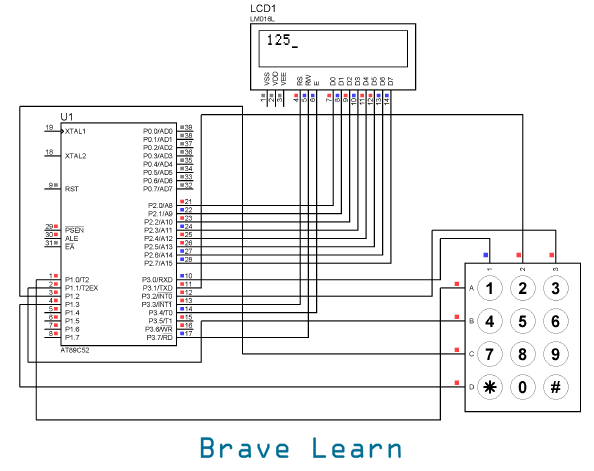
Take a look at the circuit Diagram:

Software simulation does not require external configuration of AT89C51 like crystal, reset, EA, power supply, ground etc. Please refer to datasheet on how to use AT89C51 or search bravelearn.com on how to do this
Benefits of using Keypad:
- Keypads can be used to design calculator with AT89C51
- to dial a phone number in a mobile phone
- to use in a security system like entering a password and opening a door.
- to save a variable value and much more.
Code that is used to interface this keypad and LCD with AT89C51 is given below both in C and Assembly language. Please burn the code using appropriate burner like G540 etc. To know how to burn code with G540 please visit here.
Code in C Language:
#include reg51.h

  //LCD
sbit rs = P3^3;        //register select pin
sbit rw = P3^7;        //read write pin
sbit e = P3^4;        //enable pin
sbit a = P1^0;		 //defines row A
sbit b = P1^1;		 //defines row B
sbit c = P1^2;		 //defines row C
sbit d = P1^3;		 //defines row D
sbit one = P3^0;	//defines column one
sbit two = P3^1;    //defines column two
sbit three = P3^2;   //defines column three

void delay(unsigned int time)    //Function to provide time delay in msec.

{
int i,j ;
for(i=0;i<time;i++)
 for(j=0;j<1275;j++);
}

void lcdcmd(unsigned char item)    //Function to send command to LCD

{
P2 = item;
rs= 0;
rw=0;
e=1;
delay(1);
e=0;
return;
}

void lcddata(double item)    //Function to send data to LCD

{

P2 = item;
rs= 1;
rw=0;
e=1;
delay(1);
e=0;
return;
}

int read_num(){
 //make all rows HIGH first
  a = 1;
  b = 1;
  c = 1;
  d = 1;
  //check colomn by colomn to search for pressed key
  one = 0;	//Make column one LOW and search for keys press 1,4,7,*
  two = 1;	//Others remain HIGH
  three = 1;	//Others remain HIGH
   if (a == 0) //If row A gets low means 1 is pressed
    {return '1';}
   if (b == 0) //If row B gets low means 4 is pressed
    {return '4';}
   if (c == 0)  //If row C gets low means 7 is pressed
    {return '7';}
   if (d == 0)  //If row D gets low means * is pressed
    {return '*';}
   //similar process for other keys
   one = 1;
   two = 0;
   three = 1;

   if (a == 0)
    {return '2';}
   if (b == 0)
    {return '5';}
   if (c == 0)
    {return '8';}
   if (d == 0)
    {return '0';}

	one = 1;
	two = 1;
	three = 0;
   if (a == 0)
    {return '3';}
   if (b == 0)
    {return '6';}
   if (c == 0)
    {return '9';}
   if (d == 0)
    {return '#';}
 return -1;         //if no button is pressed return -1
  }


void main()
{
int number;
lcdcmd(0x0E);    //turn display ON for cursor blinking
lcdcmd(0x01);    //clear screen
lcdcmd(0x06);    //display ON
while(1){		//Enters in infinte loop
number = read_num();	 //reads the key pressed from keypad and stores it in number
while(number == -1){	 //if no key is pressed reads the number again from keypad
  number = read_num();
 }
 if (number != -1)	  //if there is a number pressed then displays on LCD -1 means no button is pressed
  lcddata(number);
  delay(100);
}
}
Code in Assembly Language:
ORG 00H
MOV R7,#0FFH
CALL LCD
FIRST : CALL WAIT_OPEN
CALL DELAY
K1 : CALL WAIT_PRESS
CALL DELAY
MOV A,P3
ANL A,#00000111B
CJNE A,#00000111B,FIND
SJMP K1
FIND : CALL DELAY
CALL ROW_SEARCH
CJNE R7,#0FFH,EXIT1
AGAIN : RRC A
JNC FOUND
INC DPTR
JMP AGAIN
FOUND : CLR A
MOVC A,@A+DPTR
CALL DATA_SEND
EXIT1 : JMP FIRST
;***********************
LCD : MOV A,#30H
CALL COMMAND
MOV A,#0EH
CALL COMMAND
MOV A,#01H
CALL COMMAND
;********************
WAIT_OPEN : MOV P3,#0FFH
HERE : MOV P1,#00H
MOV A,P3
ANL A,#07H
CJNE A,#07H,HERE
RET
;**********************
WAIT_PRESS : MOV A,P3
ANL A,#07H
CJNE A,#07H,NEXT
SJMP WAIT_PRESS
NEXT : RET
;*********************
ROW_SEARCH :
MOV P1,#11111110B
     MOV A,P3
     ANL A,#00000111B
     CJNE A,#00000111B,ROW0
     MOV P1,#11111101B
     MOV A,P3
     ANL A,#00000111B
     CJNE A,#00000111B,ROW1
     MOV P1,#11111011B
     MOV A,P3
     ANL A,#00000111B
     CJNE A,#00000111B,row2
     MOV P1,#11110111B
     MOV A,P3
     ANL A,#00000111B
     CJNE A,#000000111B,ROW3
     MOV R7,#00H
     JMP LAST
ROW0:MOV DPTR,#KCODE0
     JMP LAST
ROW1:MOV DPTR,#KCODE1
     JMP LAST
ROW2:MOV DPTR,#KCODE2
     JMP LAST
ROW3:MOV DPTR,#KCODE3
     JMP LAST
LAST : RET
;***************************
DELAY:
      MOV R2,#10
AGAIN2: MOV R3,#250
HERE2: DJNZ R3,HERE2
      DJNZ R2,AGAIN2
       RET
;*************************
DATA_SEND : CJNE A,#01H,THERE
CALL COMMAND
JMP FINI
THERE : CJNE A,#10H,SEND
CALL COMMAND
CALL DELAY
MOV A,#20H
CALL SEND
CALL DELAY
MOV A,#10H
CALL COMMAND
CALL DELAY
JMP FINI
SEND : CALL READY
MOV P2,A
SETB P0.1
CLR P0.2
SETB P0.0
CLR P0.0
FINI : RET
;********************
COMMAND : CALL READY
MOV P2,A
CLR P0.1
CLR P0.2
SETB P0.0
CLR P0.0
RET
;*************
READY:
     SETB P2.7
     CLR P0.1
     SETB P0.2
BAK : CLR P0.0
     SETB P0.0
     JB P2.7,BAK
      RET
;**************
ORG 200H
KCODE0:DB 31H,32H,33H
KCODE1:DB 34H,35H,36H
KCODE2:DB 37H,38H,39H
KCODE3:DB 01H,30H,10H
      END
Have a Good Luck! running this simple project 🙂
If you have any suggestions or questions leave us a comment below:
